en
en
 English
 繁体中文
繁体中文 Japanese
 Korean
 Russian
 German
News
Deepen Optoelectronic Resources, Lead Technological Breakthroughs


Deepen Optoelectronic Resources, Lead Technological Breakthroughs

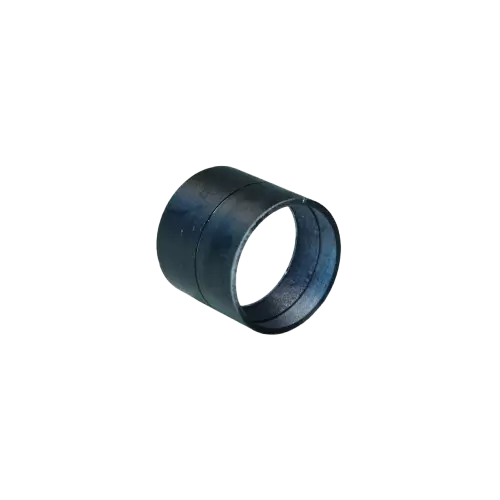
In modern photonics systems, selecting a plano convex cylindrical lens is no longer a simple component-level purchasing decision. For optical instrument manufacturers, laser system integrators, machine vision developers, and scientific laboratories, the true value of a plano convex cylindrical lens for sale is determined by how precisely it controls wavefront transformation, energy redistribution, and astigmatic separation within a complete optical system.
In high-performance laser and imaging systems, engineers are no longer asking:
“Does this lens form a line?”
Instead, they are asking:
“How stable is the line intensity profile across the entire focal plane under real operating conditions?”
This shift marks the transition from component thinking to system-level optical engineering.
A plano convex cylindrical lens operates by focusing light in only one axis while leaving the orthogonal axis unchanged. This creates a controlled transformation from:
Point source → line image
Collimated beam → elliptical beam
Gaussian spot → anisotropic intensity distribution
This anisotropic focusing behavior is essential in:
laser line scanning systems
machine vision illumination
spectral slit illumination
beam shaping in laser diode modules
The focusing behavior is governed by the cylindrical curvature radius (R) and refractive index (n):
Shorter focal length → stronger line compression
Longer focal length → more gradual line expansion
However, in real systems, focal length alone is insufficient. Engineers must also consider:
beam divergence input
aperture truncation effects
wavefront curvature mismatch
Wavefront quality defines system performance more than any geometric parameter.
Typical industrial standards:
λ/2 @ 632.8 nm → standard precision systems
λ/4 @ 632.8 nm → high-end imaging or laser systems
Wavefront deviation results in:
focal line distortion
uneven intensity distribution
reduced imaging resolution
Because cylindrical lenses focus only in one axis, astigmatism is inherent. The engineering challenge is control, not elimination.
Poor design or manufacturing leads to:
dual focal planes
asymmetric line intensity
energy dispersion at focal edges
High-precision systems require controlled astigmatic separation rather than random distortion.
To understand cylindrical lens performance, engineers must consider the full beam shaping chain:
Each stage introduces:
divergence modification
wavefront curvature changes
intensity redistribution
The cylindrical lens acts as a 1D Fourier transformer of optical energy.
Defined as:
input beam height vs output line width
This ratio determines:
line sharpness
energy density distribution
resolution in scanning systems
Uneven intensity often arises from:
surface slope errors
coating non-uniformity
substrate refractive index variations
Material selection defines system limits more than geometry.
cost-efficient
visible spectrum applications
moderate laser damage threshold
high thermal stability
excellent UV–NIR transmission
preferred in high-power laser systems
low dispersion
excellent IR transmission
used in spectroscopy and infrared imaging
CO₂ laser compatibility
high IR transmission
lower mechanical hardness
In high-energy systems:
thermal lensing becomes critical
coating absorption leads to localized heating
substrate homogeneity affects beam stability
Fused silica is generally preferred for high-power beam shaping systems due to its stability under thermal load.
Choosing a plano convex cylindrical lens manufacturer is essentially choosing a process control system.
ECOPTIK is a 15-year optical manufacturing company specializing in:
cylindrical lenses
spherical optics
prisms
filters
micro optical components
Materials sourced from:
Schott
CDGM
Corning
Sapphire
CaF₂ / MgF₂ / ZnSe / Si
ECOPTIK ensures optical precision using:
ZYGO laser interferometers → wavefront measurement
ZEISS CMM Spectrum → geometric tolerance control
Agilent Cary 7000 UMS → spectral transmission validation
This enables full lifecycle control of each plano convex cylindrical lens for sale.
Surface quality directly influences system contrast and efficiency.
40–20 → high precision laser systems
60–40 → general industrial optics
Surface defects cause:
stray light noise
reduced image contrast
energy diffusion in beam shaping
Key tolerances include:
Diameter: +0.0 / -0.1 mm
Focal length: ±1% to ±3%
Surface accuracy: λ/2 or λ/4
Why it matters:
In multi-lens systems, tolerance accumulation leads to:
beam misalignment
focal plane shift
degraded system repeatability
Used in:
industrial inspection
conveyor detection
barcode scanning systems
Requirement:
uniform line intensity distribution
stable width across scan range
Used in:
defect detection
precision measurement systems
high-speed imaging
Requirement:
high contrast
minimal optical noise
Used in:
display systems
laser alignment tools
industrial marking systems
Requirement:
controlled beam aspect ratio transformation
Used in:
spectroscopy slit illumination
research laser setups
biomedical imaging systems
Requirement:
wavefront stability and repeatability
Final system performance depends on three layers:
transmission range
thermal stability
laser damage threshold
surface accuracy
curvature precision
coating uniformity
alignment tolerance
beam propagation behavior
wavefront interaction
Weakness in any layer degrades overall optical performance.
When selecting a plano convex cylindrical lens for sale, engineers should evaluate:
wavefront error stability (not just focal length)
energy distribution uniformity across focal line
astigmatism behavior under real system conditions
batch-to-batch manufacturing consistency
material suitability for wavelength and power level
A plano convex cylindrical lens is not a simple focusing element—it is a directional wavefront transformation device used to reshape optical energy in one axis while maintaining system coherence.
The real engineering value is defined by:
wavefront control capability
astigmatism management
energy distribution uniformity
long-term optical stability under real operating conditions
In advanced photonic systems, the difference between standard and high-performance outcomes is determined at the manufacturing precision + system integration level, not at the catalog specification level.

Calcium fluoride (CaF2) crystals play an irreplaceable role in the high-end optical field due to their unique optical properties. Its core advantages lie in its deep ultraviolet transmission capability and optical isotropy (without birefringence), making it the preferred material in multiple key fields.
High-performance optical systems are no longer evaluated solely by focal length or magnification. As industrial inspection, machine vision, microscopy, spectroscopy, and scientific imaging continue to demand higher spatial resolution and greater measurement accuracy, optical designers are placing increasing emphasis on chromatic correction, wavefront quality, imaging consistency, and long-term optical stability.
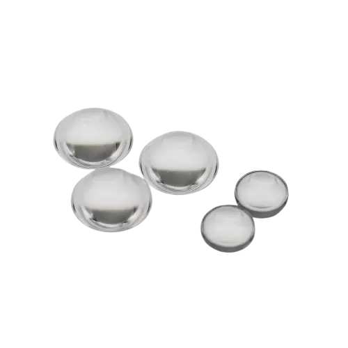
In many optical systems, the limitation is no longer the optical design itself but the ability to manufacture the lens surface with enough accuracy. Laser systems, semiconductor inspection equipment, aerospace optics, and high-resolution imaging platforms increasingly require aspherical lenses with tighter tolerances, lower scattering, and better wavefront control.