

 en
 English
 繁体中文
 Japanese
 Korean
 Russian
 German
News
Deepen Optoelectronic Resources, Lead Technological Breakthroughs


Deepen Optoelectronic Resources, Lead Technological Breakthroughs
High-quality optical lenses do not automatically produce high-quality images. Even when individual optical elements meet their specified surface accuracy and coating requirements, errors during assembly can compromise the performance of the entire optical system. Incorrect lens positioning, optical axis deviation, inaccurate air spacing, dust contamination, and mechanical stress can all affect the final imaging result.
These issues become particularly important in multi-element lens systems used in industrial vision equipment, medical optical devices, camera modules, and precision optical instruments. A small assembly deviation can introduce aberrations, reduce image sharpness, affect focus consistency, or cause performance differences between production batches.
Professional Lens Assembly Service addresses these challenges by combining precision positioning, optical alignment, mechanical integration, and performance verification. The objective is not simply to install several optical elements into a barrel, but to ensure that the assembled lens system performs according to its optical design and application requirements.
For OEM and ODM buyers, understanding the manufacturing process is equally important when evaluating Lens assembly service price and Lens assembly service cost. Assembly complexity, alignment requirements, inspection procedures, and production volume all influence the final quotation.
Lens assembly is a precision manufacturing process involving multiple operations. Each operation must be controlled according to the optical prescription, mechanical drawings, and specified assembly tolerances.
Before assembly, optical elements must be inspected and cleaned to remove dust, fingerprints, particles, and other contaminants.
Contamination on an optical surface can scatter incoming light, reduce transmission, and introduce unwanted image artifacts. In systems with multiple optical elements, contamination can accumulate across several surfaces and become increasingly difficult to identify after final assembly.
Cleaning procedures depend on the optical material, coating type, and component design. Optical-grade cleaning solutions, lint-free materials, controlled handling procedures, and appropriate inspection equipment are commonly used.
Clean assembly conditions are particularly important for medical imaging equipment, precision inspection systems, and high-resolution camera modules.
Lens positioning determines where each optical element sits within the assembled optical system.
Two important parameters are axial positioning and radial positioning.
Axial positioning controls the distance between optical elements along the optical axis. In multi-element systems, this distance is commonly referred to as the air gap or inter-element spacing.
Radial positioning determines whether each lens is correctly centered relative to the mechanical reference axis or optical axis.
Incorrect spacing can change the effective optical behavior of a lens system, including its focal position and aberration characteristics. Similarly, radial positioning errors can introduce decentering and contribute to asymmetric image degradation.
The acceptable tolerances depend on the optical design. A compact imaging lens and a precision measurement objective may require very different positioning strategies.
For this reason, professional assembly should follow the specified optical and mechanical drawings rather than apply a universal spacing or positioning tolerance.
Optical axis alignment is one of the most important operations in precision lens assembly.
Ideally, the optical axes of individual elements should maintain the relationship defined by the optical design. However, manufacturing tolerances, mechanical clearances, barrel geometry, and assembly errors can introduce decentering or tilt.
These errors can affect:
Image resolution: Misaligned elements can increase optical aberrations and reduce the system's ability to resolve fine details.
MTF performance: Decentering and tilt may reduce contrast transfer, particularly toward the image field edges.
Distortion: Incorrect element positioning can alter the designed distortion characteristics.
Focus consistency: Alignment errors may create differences in image quality across the field.
System stability: Poor mechanical positioning can make the optical configuration more sensitive to vibration and temperature changes.
It is important to distinguish optical axis alignment from mechanical concentricity. A component can be mechanically centered within a barrel without achieving the intended optical alignment.
This is why precision optical assembly may require dedicated alignment equipment and optical performance feedback.
The lens barrel provides the mechanical reference structure that holds optical elements in their designed positions.
Its internal diameter, shoulder geometry, thread accuracy, surface finish, and dimensional consistency can influence assembly quality.
For example, an inaccurate seating shoulder may cause a lens to tilt when installed. Excessive clearance can introduce positioning uncertainty, while insufficient clearance may create unwanted mechanical stress.
Common mechanical assembly methods include:
Precision threaded assembly
Spacer-based positioning
Mechanical retaining rings
Optical adhesive bonding
Custom-designed positioning structures
The appropriate method depends on the lens structure, mechanical requirements, environmental conditions, and expected production process.
After positioning and alignment, optical elements must be secured without introducing unacceptable stress.
Optical adhesive bonding is suitable for certain assemblies requiring permanent fixation or specialized positioning. However, adhesive selection, application quantity, curing conditions, and material compatibility must be considered.
Threaded assembly offers mechanical adjustability and can be useful in optical systems requiring controlled positioning or servicing.
Some lens systems also require final focusing or mechanical adjustment after initial assembly. The objective is to achieve the specified image plane position and optical performance while maintaining assembly stability.
The fixing method should be selected according to the optical design rather than based solely on manufacturing convenience.
Not every optical system has the same assembly priorities.
Application | Main assembly considerations |
|---|---|
Industrial vision lenses | MTF consistency, optical alignment, focus stability, and mechanical reliability |
Camera lenses | Compact structure, image sharpness, field performance, and production consistency |
Medical optical lenses | Image clarity, cleanliness, repeatability, and application-specific reliability |
Precision optical instruments | Alignment accuracy, optical stability, and measurement performance |
OEM/ODM optical modules | Design compatibility, customization, inspection requirements, and production scalability |
A suitable assembly process must reflect the actual application, optical prescription, and operating environment.
A professional Lens Assembly Service provider should offer more than basic mechanical installation. The service needs to connect optical design requirements with practical manufacturing processes and measurable quality control.
Passive alignment and active alignment are two important approaches used in optical assembly.
Passive Alignment
Passive alignment positions optical components according to predetermined mechanical references, precision fixtures, locating structures, and dimensional tolerances.
The method relies on the accuracy of the components and assembly tooling rather than continuously adjusting the optical position based on live imaging feedback.
It is suitable for lens systems with well-defined mechanical datums, repeatable component dimensions, and established assembly tolerances.
Its advantages include:
Relatively straightforward process standardization
Good compatibility with repeat production
Reduced dependence on real-time optical adjustment
Potentially higher throughput in suitable automated processes
However, passive alignment is only effective when the mechanical references accurately represent the required optical positioning.
Active Alignment
Active alignment uses optical or imaging feedback to adjust component positions during assembly.
Instead of relying exclusively on mechanical dimensions, the process evaluates actual optical performance while positioning or adjusting the components.
Depending on the system, the adjustment may involve lateral positioning, axial movement, tilt correction, or other degrees of freedom.
Active alignment is particularly useful when mechanical tolerances alone cannot consistently achieve the required optical performance.
Its advantages include:
Compensation for certain accumulated assembly errors
Direct evaluation of optical performance
Improved alignment flexibility
Suitability for demanding optical assemblies
However, active alignment generally involves additional equipment, adjustment time, and process development.
Neither method is universally superior. Passive alignment is often appropriate for repeatable mechanical designs, while active alignment is valuable when optical feedback is necessary to achieve the required performance.
Some production processes also combine both approaches: passive positioning establishes the initial geometry, followed by active adjustment and final fixation.
Precision positioning equipment helps control component location during assembly.
Depending on the project, the equipment may include precision fixtures, alignment stages, optical measurement instruments, and dedicated assembly tooling.
The assembly procedure should define:
Component orientation and installation sequence
Axial and radial positioning references
Required centering and tilt controls
Adhesive or mechanical fixation procedures
Adjustment and inspection checkpoints
For multi-element lens systems, assembly sequence is particularly important because positioning errors in early stages can affect subsequent components.
A documented process helps reduce operator-dependent variation and improves repeatability during production.
Mechanical inspection alone cannot establish whether an assembled lens meets its optical performance requirements.
A suitable inspection plan should be developed according to the lens design and customer specifications.
Common inspection items include:
Inspection item | What it evaluates |
|---|---|
Focal length | Whether the assembled system meets its specified effective focal length |
Resolution | The ability to distinguish fine image details |
MTF | Contrast transfer at specified spatial frequencies |
Transmittance | The amount of light transmitted through the optical system |
Stray light | Unwanted light that can reduce image contrast |
Image quality | Overall imaging performance under specified test conditions |
Mechanical dimensions | Compatibility with the required mechanical interface |
Not every lens requires every test. For example, a project focused on imaging resolution may prioritize MTF and image quality, while another optical assembly may require particular attention to transmission or stray-light performance.
Testing conditions also matter. MTF results depend on factors such as wavelength, spatial frequency, field position, focus condition, and measurement configuration.
Therefore, inspection reports should identify the relevant test conditions and acceptance criteria instead of presenting isolated measurement values.
OEM and ODM buyers often have different optical designs, mechanical interfaces, production quantities, and inspection requirements.
A professional assembly provider should be able to evaluate project documentation before selecting a manufacturing process.
Typical inputs include:
Optical design specifications
Lens element drawings
Lens barrel drawings
Material and coating information
Assembly tolerance requirements
Required optical performance
Environmental and mechanical conditions
Prototype and production quantities
Based on these inputs, the supplier can determine whether passive alignment, active alignment, adhesive bonding, threaded assembly, or a combined approach is appropriate.
Prototype development may also require process verification before moving into repeat production.
For volume manufacturing, the assembly process should be standardized through documented procedures, inspection checkpoints, and consistent tooling.
This approach helps maintain product quality as production quantities increase.
ECOPTIK — Innovative and Enterprising Your Optical Customization Partner has 15 years of experience researching optical component fabrication technology.
The company manufactures a range of precision optical components, including domes, spherical lenses, micro-optical components, cylindrical mirrors, filters, prisms, and optical windows.
Its available material options include optical glass from Schott, CDGM, and Corning, as well as sapphire, CaF2, MgF2, fused silica, silicon, ZnSe, and ZnS.
In addition to optical component manufacturing, ECOPTIK offers Lens Assembly Service for customers requiring optical components to be integrated into functional lens systems.
Its testing equipment includes:
ZYGO laser interferometers: Used for relevant optical surface and wavefront measurements.
ZEISS CMM Spectrum: Used for dimensional measurement and geometric inspection.
Agilent Cary 7000 UMS: Used for applicable optical measurement and material characterization requirements.
These instruments support different stages of optical manufacturing and inspection. The specific tests and reports provided for an assembled lens depend on the component design, project requirements, and agreed inspection scope.
For OEM and ODM customers, combining optical component fabrication with assembly services can simplify technical coordination between component specifications and downstream integration requirements.
For optical equipment manufacturers and purchasing teams, understanding Lens assembly service price requires looking beyond the number of assembly operations.
The quotation reflects the technical difficulty of the optical system, the resources needed to assemble it, and the inspection requirements necessary to verify the final product.
The number of optical elements is one factor influencing assembly cost, but it is not the only consideration.
A simple lens assembly may require relatively straightforward positioning and mechanical fixation.
A multi-element optical system may involve:
More complex assembly sequences
Additional spacing and positioning controls
Greater sensitivity to accumulated tolerances
More demanding optical alignment
Additional inspection and adjustment operations
Consequently, two assemblies containing the same number of lenses may still have significantly different manufacturing costs.
The optical prescription, mechanical structure, and required performance are more important than component quantity alone.
Tighter assembly tolerances generally increase process difficulty.
When a project requires more demanding centering, tilt, spacing, or focus control, the supplier may need more precise fixtures, additional adjustment stages, specialized equipment, and more extensive inspection.
Active alignment can also increase processing time because each assembly may require individual optical adjustment.
The actual cost depends on the required alignment strategy and whether the process can be standardized for repeated production.
Buyers should therefore provide measurable assembly tolerances instead of simply requesting high precision.
Optical materials influence assembly considerations through their physical and thermal properties.
For example, differences in thermal expansion between optical elements, adhesives, and mechanical structures may affect assembly stability under changing temperatures.
Certain materials or coatings may also require more specialized handling and cleaning procedures.
The lens barrel material, adhesive compatibility, and fixation design should therefore be considered together.
A material selection that reduces manufacturing complexity or improves mechanical compatibility may help control overall assembly cost.
Inspection scope is another important pricing factor.
A project requiring dimensional inspection and basic visual examination generally involves a different workload from one requiring detailed MTF measurements, focal length verification, stray-light evaluation, and individual optical performance reports.
Additional inspection requirements may involve:
Specialized measurement equipment
Dedicated test fixtures
Additional setup and calibration
More inspection time per unit
Detailed documentation and traceability
Buyers should identify mandatory acceptance tests during the quotation stage. This helps prevent differences between the supplier's assumed inspection scope and the customer's actual requirements.
Production quantity changes how manufacturing resources are distributed across each unit.
Production stage | Main cost considerations |
|---|---|
Prototype development | Process evaluation, fixture preparation, engineering time, and individual adjustments |
Small-batch production | Setup costs, manual operations, inspection workload, and limited economies of scale |
Mass production | Tooling investment, process standardization, automation, yield control, and unit cost optimization |
Prototype orders often have higher unit costs because engineering and setup expenses are distributed across relatively few products.
Small-batch production can reduce some development expenses but may still involve substantial manual assembly and inspection.
In mass production, repeatable assembly procedures, dedicated tooling, and appropriate automation can reduce labor requirements and improve consistency.
However, mass production does not automatically guarantee lower total costs. If the design requires extensive active alignment or strict individual testing, these operations may remain significant cost drivers.
Purchasing teams can improve cost efficiency without compromising necessary optical performance.
Several practical approaches are worth considering.
First, optimize the optical and mechanical design together. A lens structure with clearly defined mechanical references may simplify positioning and reduce unnecessary alignment adjustments.
Second, establish realistic tolerances. Extremely tight tolerances should only be specified where the optical design and application require them. Unnecessary tolerance restrictions can increase machining, assembly, and inspection costs.
Third, select appropriate alignment methods. Passive alignment may be sufficient for certain repeatable designs, while active alignment should be reserved for applications where optical feedback provides meaningful value.
Fourth, define inspection requirements clearly. Testing should focus on the performance characteristics that determine product acceptance rather than adding unnecessary inspection operations.
Finally, plan production quantities carefully. Early coordination between prototype development and future production can reduce repeated tooling preparation and process changes.
A reliable quotation should explain the relationship between technical requirements, manufacturing operations, inspection scope, and production volume.
Selecting a professional Lens Assembly Service provider requires more than comparing quotations. Optical positioning, axis alignment, spacing control, mechanical fixation, and final performance verification all influence the quality of the assembled lens system.
For optical equipment manufacturers, camera module producers, industrial vision companies, and medical device manufacturers, the right assembly solution must match the actual optical design and application requirements.
ECOPTIK combines precision optical component manufacturing experience with lens assembly capabilities and specialized testing equipment to support customized optical projects. Its material options, component fabrication experience, and inspection resources provide a foundation for coordinating optical component requirements with downstream assembly needs.
When evaluating Lens assembly service price and Lens assembly service cost, buyers should provide their optical drawings, mechanical specifications, required tolerances, inspection criteria, and expected production quantities.
With these details, a qualified supplier can assess the assembly process, recommend suitable alignment methods, define the inspection scope, and prepare a quotation based on the actual technical requirements of the project.
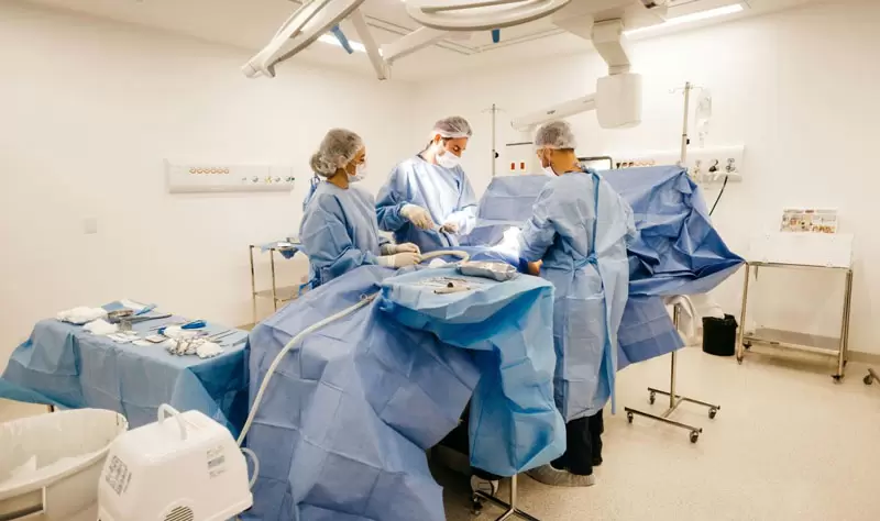
3D endoscope technology has become one of the indispensable and important tools in modern medicine. It enables doctors to observe and manipulate organs and tissues in the patient's body in real-time during surgery by utilizing advanced optical and imaging technologies.
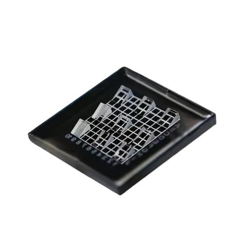
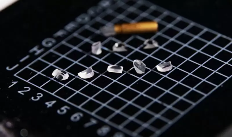
In compact optical instruments, the challenge is often not generating or transmitting light, but finding enough space to route it accurately. Conventional-size prisms can become difficult to integrate into endoscopes, laser diode (LD) to fiber coupling assemblies, and other precision instruments where every millimeter of mechanical space matters.
Endoscope is a medical tool used to examine organs and tissues inside the human body. It consists of a soft long tube with a small light source and camera at one end, which can transmit images to a display for doctors to observe.