

 en
en
 English
 繁体中文
繁体中文 Japanese
 Korean
 Russian
 German
News
Deepen Optoelectronic Resources, Lead Technological Breakthroughs

Deepen Optoelectronic Resources, Lead Technological Breakthroughs
Spherical lens coating directly affects how efficiently an optical system transmits light, controls reflections, and maintains image quality over time. An uncoated lens can lose a meaningful portion of incident light through surface reflections, while an unsuitable or poorly controlled coating may introduce stray light, inconsistent transmission, surface defects, or premature coating failure.
For machine vision equipment, laser systems, precision measurement instruments, and scientific optical assemblies, these issues can reduce image contrast, affect measurement repeatability, and compromise system reliability. Selecting the best spherical lens coating therefore requires more than choosing an anti-reflective coating with a low nominal reflectance. Engineers and purchasing teams must evaluate wavelength range, angle of incidence, substrate compatibility, coating uniformity, adhesion, environmental resistance, and the optical system's operating conditions.
Understanding each factor also helps identify the causes of a spherical lens coating problem before it affects production or field performance.
The best coating depends on the optical function required by the system. Anti-reflective coatings are commonly selected to increase transmission, while high-reflectivity coatings are designed to return light efficiently at specified wavelengths and angles. Other functional coatings may provide spectral filtering or additional surface protection, depending on the design.
An anti-reflective (AR) coating uses thin-film interference to reduce reflected light. By selecting suitable materials and controlling their refractive indices and optical thicknesses, the coating can make reflected waves interfere destructively over a designed wavelength range.
A single-layer AR coating can be effective near a selected wavelength, but its performance may decline away from that design point. Multilayer AR coatings provide greater flexibility for broadband applications, although their performance depends on the layer sequence, material properties, manufacturing tolerances, and operating conditions.
For a lens with two air-to-glass surfaces, reducing reflection at both surfaces can improve overall transmission. However, the actual gain depends on the uncoated substrate's refractive index, the coating design, absorption, and measurement conditions.
Lower reflectance can also reduce ghost images and unwanted reflections in imaging systems. Nevertheless, stray-light performance depends on the entire optical assembly, including lens geometry, surface quality, mechanical design, and internal reflections. An AR coating alone cannot eliminate every source of stray light.
High-reflectivity coatings are appropriate when the optical system needs to redirect or retain light rather than maximize transmission. Dielectric multilayer coatings can achieve high reflectance within a specified spectral band, while metallic coatings may offer broader spectral coverage with different reflectance and durability characteristics.
Other functional coatings include wavelength-selective filters and protective overcoats. Their suitability depends on the required optical function and the compatibility of the coating stack with the substrate and operating environment.
| Coating type | Primary function | Key selection consideration |
|---|---|---|
| Single-layer AR | Reduce reflection near a design wavelength | Spectral bandwidth and incidence angle |
| Multilayer AR | Reduce reflection over a wider or tailored band | Spectral response, polarization, and layer control |
| Dielectric high-reflectivity | Reflect selected wavelengths efficiently | Design wavelength, angle, and laser conditions |
| Metallic reflective | Provide reflection across a broader spectral region | Reflectance, absorption, and environmental protection |
| Functional or protective coating | Provide spectral selectivity or surface protection | Required function and compatibility with other layers |
No coating type is universally superior. The appropriate choice is the one that satisfies the optical performance requirements without introducing unacceptable durability, manufacturing, or integration risks.
The operating wavelength is one of the first parameters that should be established.
Ultraviolet optics: UV applications require coating materials with suitable transparency, absorption characteristics, and stability in the target wavelength range. Substrate selection is equally important because substrate absorption can limit system transmission regardless of coating quality.
Visible-light optics: Machine vision cameras, inspection systems, and scientific instruments often need controlled reflection across a defined visible band. Broadband AR designs may be preferable when illumination and detection wavelengths vary.
Near-infrared optics: NIR imaging and sensing systems require coatings designed for their actual operating band, not simply a visible-light coating assumed to work at longer wavelengths.
Infrared optics: IR applications require substrate and coating materials with suitable spectral transmission and absorption characteristics. Materials that perform well in the visible spectrum may not be appropriate in the infrared.
The coating specification should identify the wavelength range and, where necessary, the spectral measurement interval. A statement such as “high transmission” is insufficient without a defined band and test conditions.
Coating performance changes with the angle of incidence. As the angle increases, the effective optical thickness and the spectral position of interference features can shift. S- and P-polarized light may also behave differently at oblique incidence.
A coating designed for near-normal incidence may therefore underperform in an optical assembly that uses a wide ray-angle distribution.
Spherical curvature creates an additional manufacturing challenge. Rays reaching different locations on a curved surface encounter different local surface normals. The deposition geometry can also produce variations in coating thickness across the aperture. These effects may create spatial differences in spectral response, especially in demanding broadband or angle-sensitive designs.
For this reason, coating evaluation should consider the actual clear aperture, surface curvature, optical path, and expected incidence-angle distribution. Where uniform performance is critical, the supplier should define the relevant aperture locations and measurement method rather than relying on a single central measurement.
A spherical lens coating problem can originate from substrate preparation, coating deposition, film design, handling, cleaning, or environmental exposure. Identifying the actual failure mechanism is essential because different defects require different corrective actions.
Visible signs: The coating separates from the substrate, often appearing as flakes, lifted edges, or localized patches.
Potential causes: Residual contamination, moisture, incompatible substrate preparation, unsuitable process conditions, excessive film stress, or incompatibility between coating layers can contribute to adhesion failure.
Inspection and corrective action: Inspect the affected area under appropriate illumination and magnification. Review cleaning records, substrate handling, deposition conditions, and any environmental exposure preceding the failure. Adhesion testing should follow an agreed method appropriate to the coating and substrate. Improve surface preparation and process control, and reassess the coating design if stress or material compatibility is implicated.
Peeling can expose the substrate and alter local reflection, potentially affecting image uniformity and long-term reliability.
Visible signs: Scratches may appear as linear marks; pinholes as small localized defects; contamination may appear as spots, haze, or irregular discoloration.
Potential causes: Handling damage, airborne particles, insufficient cleaning, fixture contamination, or defects introduced during processing may be responsible. Not every visible mark originates during deposition.
Inspection and corrective action: Use suitable bright-field or dark-field inspection, microscopy, and, where appropriate, surface-defect measurement. Distinguish coating defects from substrate scratches and removable contamination before deciding whether cleaning, rework, or replacement is appropriate.
In machine vision systems, localized defects may generate unwanted scatter or visible image artifacts. In precision measurement equipment, even small defects can matter when they fall within a critical optical path.
Visible signs: Fine cracks, crazing, or localized film separation may develop after processing or environmental exposure.
Potential causes: Excessive tensile or compressive stress, thermal expansion mismatch, unsuitable layer thicknesses, and repeated temperature changes can contribute. Substrate properties and the complete coating stack must be considered together.
Inspection and corrective action: Examine the defect pattern and determine whether it appeared after deposition, temperature cycling, or mechanical handling. Review deposition parameters and the material stack, then conduct appropriate thermal or environmental testing. Reducing stress may require changes to the deposition process or coating architecture rather than simply reducing the total film thickness.
Visible signs: Measured transmission falls below specification, reflectance is elevated, or reflection color varies across the lens.
Potential causes: Incorrect design wavelength, thickness deviations, material variation, contamination, substrate absorption, or measurement geometry can all contribute. Uneven reflection color may indicate spatial thickness variation, but appearance alone does not establish the cause.
Inspection and corrective action: Measure spectral transmission and reflectance using a calibrated spectrophotometer or another suitable instrument. Compare results against the agreed wavelength range, angle, polarization, and measurement geometry. If the results vary across the aperture, perform spatial measurements to distinguish coating nonuniformity from substrate or instrument effects.
For laser optics, verify the relevant wavelength and operating conditions rather than relying on visible reflection color as a quality indicator.
Humidity, temperature cycling, chemical exposure, and unsuitable cleaning methods may affect some coating systems. The extent of degradation depends on the coating materials, protective layers, substrate, and actual exposure conditions.
A lens that passes an initial optical inspection may still fail after repeated cleaning or prolonged environmental exposure. Where service reliability is important, specify environmental tests that reflect the intended use and remeasure optical performance afterward. A durability claim is meaningful only when the test method, exposure conditions, and acceptance criteria are defined.
Choosing a supplier should involve a review of measurable optical performance and process capability, not just a product description or initial quotation.
Before requesting a coating, provide the supplier with the operating wavelength or wavelength range, required transmission or reflectance, incidence-angle range, polarization requirements where relevant, substrate material, surface curvature, clear aperture, and environmental conditions.
For laser applications, also specify wavelength, beam characteristics, operating power or pulse conditions, and the required laser-induced damage threshold (LIDT). LIDT depends on test conditions, including pulse duration, repetition rate, beam size, and test protocol. It should not be treated as a universal material rating.
The coating specification should distinguish between average and minimum performance where appropriate. A broadband coating's average transmission, for example, may conceal a local dip within a critical wavelength region.
A practical inspection plan may include:
Spectral transmission and reflectance: Verify optical performance across the specified wavelength range using a suitable calibrated instrument.
Spatial uniformity: Measure at defined locations across the clear aperture when the application requires consistent performance over the curved surface.
Surface inspection: Check for scratches, pinholes, contamination, cracks, and other defects against agreed acceptance criteria.
Adhesion and abrasion resistance: Use suitable standardized or customer-agreed tests. Tape, scratch, or abrasion tests are not interchangeable, and the method must be appropriate for the coating system.
Environmental testing: Apply relevant temperature, humidity, or cleaning-cycle tests and compare optical measurements before and after exposure.
Laser damage testing: For laser applications, use a documented test protocol that matches the intended operating conditions as closely as practical.
Test reports should identify the measurement method, test conditions, sample configuration, and acceptance criteria. This information makes supplier results more useful for technical qualification and incoming inspection.
For industrial cameras and automated inspection, prioritize the spectral response of the illumination and sensor, control of ghost reflections, and consistency across the usable aperture. For laser systems, wavelength-specific performance, damage resistance, and the actual angle of incidence are critical. Precision metrology may require low wavefront error and controlled coating-induced effects in addition to transmission. Scientific instruments may need broadband performance or stable spectral behavior under controlled environmental conditions.
Procurement teams should also consider batch consistency, documentation, lead time, and the supplier's ability to manufacture the required geometry repeatedly. The lowest quoted price may not represent the lowest total cost if incoming inspection failures, rework, or field replacement become frequent.
A reliable coating solution starts with a complete optical specification and a manufacturing process that can be verified. Substrate quality, cleaning, fixture design, deposition control, coating stress, inspection, and handling all contribute to the final result.
ECOPTIK has 15 years of experience researching optical component fabrication technology and serves as an optical customization partner. Its product range includes domes, spherical lenses, micro-optical components, cylindrical mirrors, filters, prisms, and windows. Available material options include glass from SCHOTT, CDGM, and Corning, as well as sapphire, CaF₂, MgF₂, fused silica, silicon, ZnSe, and ZnS. Material suitability depends on the required wavelength, optical function, and operating environment.
For optical measurement and quality reporting, ECOPTIK possesses ZYGO laser interferometers, a ZEISS CMM Spectrum, and an Agilent Cary 7000 UMS. These instruments support different measurement tasks; the appropriate method depends on whether the requirement concerns wavefront or surface-related characteristics, dimensional inspection, or optical properties. Their availability should not be interpreted as proof that every coating parameter is measured by every instrument.
ECOPTIK also offers lens assembly services, which can help customers coordinate component requirements with optical-system integration. For a project involving a spherical lens coating problem, a useful starting point is to share the substrate, lens drawing, target wavelength, performance specification, operating environment, and observed defect or failure history. This allows the required coating design and verification plan to be evaluated against the actual application.
The best spherical lens coating is the coating system that meets the application's optical requirements while maintaining acceptable adhesion, uniformity, and environmental stability. AR coatings can reduce reflection and improve transmission, while high-reflectivity and other functional coatings serve different optical purposes. Their performance depends on wavelength, incidence angle, substrate, curvature, film structure, and manufacturing control.
When a spherical lens coating problem occurs, the correct response is to identify the defect, verify its optical or mechanical impact, and investigate the likely cause through appropriate inspection and testing. For optical manufacturers and equipment buyers, clearly defined specifications and documented test results provide a stronger basis for supplier selection than broad claims of high quality or durability.
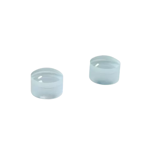
A conventional singlet lens can be sufficient for simple focusing or collimation, but its limitations become more apparent when an optical system must work across multiple wavelengths. Because different wavelengths are refracted by different amounts, blue, green, and red light may form their focal points at different axial positions.
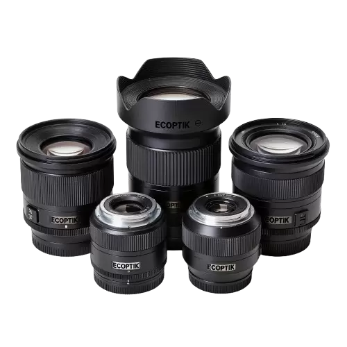
Standard optical lenses are designed around common imaging conditions, but many industrial and scientific systems operate within much tighter optical and mechanical constraints.
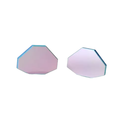
Modern laser processing systems are expected to achieve higher throughput while maintaining consistent positioning accuracy. However, many traditional laser scanning solutions face limitations when operating at high speeds.