

 en
en
 English
 繁体中文
繁体中文 Japanese
 Korean
 Russian
 German
News
Deepen Optoelectronic Resources, Lead Technological Breakthroughs

Deepen Optoelectronic Resources, Lead Technological Breakthroughs
In precision machine vision, the lens can become a limiting factor even when the camera sensor and image-processing software are capable of resolving small dimensional differences. A conventional lens changes its apparent magnification as the object moves closer to or farther from the lens. This perspective effect means that the measured diameter of a hole, the position of an edge, or the width of a mechanical component can change in the image even when the physical dimension has not changed.
This problem becomes more significant when parts are not positioned at exactly the same height or when a production line has unavoidable variations in object distance. Image distortion can introduce another source of measurement error, particularly toward the edges of the field of view.
A telecentric lens addresses these limitations through its optical geometry. By controlling the chief-ray path, particularly on the object side, it can maintain much more consistent magnification over a defined working-distance range. For dimensional inspection, this makes the optical system less sensitive to small changes in object position and provides a more reliable basis for repeatable measurement.
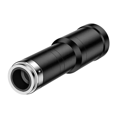
The primary reason to use a telecentric lens is not simply that it produces a sharper image. Its main advantage is controlling how object position affects the image.
With a conventional machine vision lens, two identical components positioned at different distances from the lens can appear to have different sizes. This is normal perspective projection. For applications such as counting or general presence inspection, that change may be acceptable. For dimensional measurement, however, it can directly affect the result.
An object-space telecentric lens uses an optical arrangement in which the chief rays on the object side are approximately parallel to the optical axis. As a result, lateral image size becomes substantially less dependent on small changes in object distance within the specified operating range. This is particularly useful when measuring hole diameter, outer diameter, component width, edge position, or the dimensions of molded and machined parts.
Telecentricity should therefore be considered together with magnification. A specified magnification, such as 0.5X or 1X, determines the relationship between object size and image size, while telecentricity determines how consistently that relationship is maintained when the object position changes.
Distortion is another important parameter. Even when the nominal magnification is appropriate, geometric distortion can cause the same feature to appear at different apparent scales depending on where it is located in the field of view. Low-distortion telecentric optics are therefore valuable for applications where measurements are taken across a large image area rather than only at the optical center.
Depth of field also matters. A component with height variation may not remain perfectly positioned relative to the nominal working plane. A larger usable depth of field can help maintain acceptable image quality across this variation, although increasing depth of field often requires a smaller aperture and can affect available light and exposure settings. F-number, illumination intensity, sensor sensitivity, and required inspection speed must therefore be considered together.
Object-space telecentric, image-space telecentric, and bi-telecentric designs serve different purposes. Object-space telecentricity is particularly relevant to dimensional inspection because it reduces perspective-related magnification changes on the object side. Image-space telecentricity controls the chief-ray geometry toward the sensor and can be useful for sensor-side imaging requirements. A bi-telecentric lens combines telecentric behavior on both sides and is often considered when extremely stable imaging geometry is required. The appropriate architecture depends on the measurement tolerance, sensor configuration, optical path, and mechanical arrangement of the inspection system.
The practical question is not simply what telecentric lenses can do, but when a machine vision system actually needs one.
A telecentric lens is worth considering when the measurement tolerance is tight enough that perspective-related size variation becomes significant compared with the allowable error. It is also useful when parts cannot be positioned at exactly the same height, when multiple features must be measured across a relatively large field of view, or when edge geometry must be evaluated consistently.
For electronic components, for example, inspection may involve measuring package dimensions, lead spacing, connector geometry, or the position of small features. A conventional lens can introduce apparent dimensional changes when component height varies. Telecentric imaging reduces the influence of this positional variation, allowing the image-processing software to work with a more consistent geometric representation.
Connector inspection is another common use. Pin position, housing dimensions, opening size, and edge locations may all be evaluated from a single image. The required field of view must be large enough to capture the complete component while maintaining sufficient object-space resolution for the smallest feature being measured. Choosing magnification without considering sensor size can therefore result in an unsuitable system.
Precision mechanical parts present similar requirements. Hole diameter, outer diameter, slot width, chamfer position, and component dimensions can be measured more consistently when the optical system minimizes perspective effects. This is especially relevant for automated inspection where thousands of parts must be evaluated using the same measurement criteria.
Telecentric lenses are also used in semiconductor inspection, PCB inspection, glass measurement, molded-part inspection, and automated dimensional sorting. In these applications, the lens selection should start with the measurement task rather than the camera alone.
The key parameters are interconnected:
Magnification determines how large the object appears on the sensor.
Field of view (FOV) determines the physical inspection area captured by the camera.
Working distance (WD) defines the required mechanical space between the lens and object.
Sensor size determines whether the lens can cover the camera without excessive vignetting or loss of usable image area.
Depth of field (DOF) determines how much object-height variation can remain within the acceptable imaging range.
Distortion affects geometric measurement across the field.
F-number influences depth of field, light transmission, and exposure requirements.
Resolution must be sufficient for the smallest feature and measurement tolerance.
For example, a large component does not automatically require a low-magnification lens. The correct choice depends on the sensor dimensions and required FOV. Likewise, selecting a lens with sufficient resolution but an inadequate working distance or sensor coverage can make the complete optical system unsuitable.
The practical selection process should therefore begin with the object's dimensions, smallest measurable feature, allowable measurement error, height variation, required working distance, camera sensor size, and inspection speed.
Telecentric Lens Price varies significantly because the optical system is more demanding than a conventional machine vision lens. Comparing prices based only on magnification or external appearance can therefore be misleading.
One major factor is magnification and FOV. A lens designed for a relatively small FOV may require a different optical configuration from one designed to cover a large inspection area. Large-FOV telecentric systems can require larger optical elements and more complex mechanical structures, increasing both manufacturing difficulty and material cost.
Working distance also affects the design. A long working distance may be necessary when the system includes coaxial illumination, ring lighting, mechanical fixtures, or other components between the lens and inspected part. Maintaining telecentric performance while providing a longer WD can require additional optical elements and a larger lens structure.
Sensor compatibility is another cost factor. A lens designed for a larger sensor must provide an image circle large enough to cover that sensor while maintaining the required optical performance. Camera selection and lens selection should therefore be treated as one system-design decision rather than two independent purchases.
The required level of telecentricity, distortion control, and optical resolution also influences cost. A dimensional inspection system with a tight measurement tolerance may require substantially better geometric control than an inspection system used only for presence or orientation detection.
Customization can further affect the price. Special magnification, non-standard working distance, larger image coverage, customized mechanical interfaces, specific spectral requirements, or integration with dedicated illumination can require optical redesign and additional verification.
For this reason, the lowest-priced telecentric lens is not necessarily the lowest-cost solution. A lens with unsuitable sensor coverage or working distance may require a different camera, additional optics, mechanical changes, or a revised illumination system. Calibration and system integration can add further costs.
A more useful procurement approach is to define the required measurement tolerance first, then determine the necessary magnification, FOV, sensor size, working distance, DOF, distortion level, F-number, and telecentricity. This allows buyers to avoid paying for specifications that do not contribute to the inspection task while avoiding under-specification that compromises measurement reliability.
Telecentric optics should be selected as part of the complete measurement system. Camera resolution, sensor format, illumination, mounting geometry, calibration method, and image-processing algorithms all influence the final measurement result.
For example, increasing camera resolution does not automatically improve dimensional accuracy if the lens introduces excessive distortion or if the optical magnification is poorly matched to the required FOV. Similarly, a highly telecentric lens cannot compensate for inadequate lighting when the inspected edge does not have sufficient contrast for reliable edge detection.
This is where optical customization becomes important for industrial applications with non-standard requirements.
ECOPTIK has researched optical component fabrication technology for 15 years and manufactures precision optical components including spherical lenses, dome optics, micro-optical components, cylindrical mirrors, filters, prisms, and windows. Its material options include glass from Schott, CDGM, and Corning, as well as Sapphire, CaF₂, MgF₂, Fused Silica, Si, ZnSe, and ZnS. ECOPTIK also provides lens assembly services.
For verification and product reporting, ECOPTIK uses equipment including ZYGO laser interferometers, ZEISS CMM Spectrum, and Agilent Cary 7000 UMS. These capabilities support optical testing and provide measurement reports for customized optical products.
For telecentric lens applications, ECOPTIK provides high-performance telecentric lenses and customized solutions for industrial vision and precision measurement. Its optical design approach focuses on reducing measurement inaccuracies associated with viewing-angle changes and image distortion through controlled telecentric geometry, stable imaging, and application-specific customization.
For machine vision companies, precision measurement equipment manufacturers, automation integrators, and industrial R&D organizations, the objective is not simply to purchase a telecentric lens. The objective is to establish an optical configuration in which telecentricity, magnification, FOV, working distance, DOF, distortion, sensor size, F/#, and measurement tolerance work together.
That relationship ultimately determines whether a telecentric lens is appropriate for the application—and whether its price represents an effective investment in the complete measurement system.
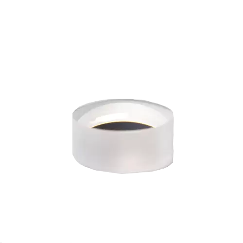
In precision optical engineering, understanding Plano concave lens uses requires moving beyond basic ray divergence concepts into system-level wavefront control.
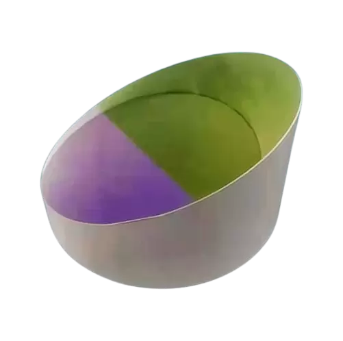
In many advanced optical systems, traditional mirrors and lenses begin to show limitations when designers need higher energy efficiency, broader wavelength compatibility, and more stable beam control. Spherical mirrors can introduce spherical aberration, while transmission lenses may suffer from chromatic effects, absorption losses, and thermal problems when exposed to high-power laser beams.
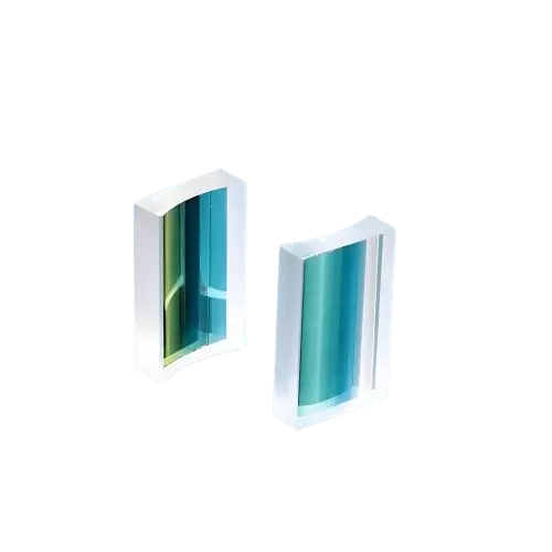
In many optical systems, beam control is required in only one direction. A laser may need to expand horizontally while retaining its original vertical dimension, or an imaging system may need to modify the width of an image without applying the same optical power to its height.