Definition of the Narrow-band Filter
The so-called narrow-band filter is subdivided from the band-pass filter and has the same definition as the band-pass filter, that is, the filter allows the light signal to pass through in a specific band, and deviates from this band. The optical signals on both sides are blocked, and the passband of the narrowband filter is relatively narrow, typically less than 5% of the center wavelength value.
Description of Parameters of Narrow-band Filter:
1. Center wavelength
The center wavelength of a narrowband filter is typically the operating wavelength of the instrument or device, which is the wavelength at the center of the passband.
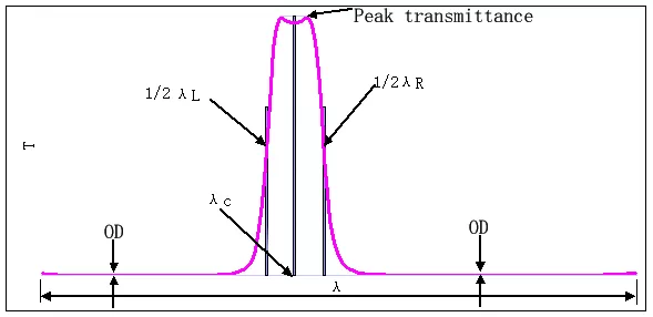
Figure 1 is a schematic diagram showing the transmittance curve of a narrow band filter.
In the figure, the specific definition of the center wavelength (λc) is as follows:
λc=(λL+λR )/2
Wherein, λL, λR respectively, the wavelength positions of the left and right sides of the passband when the transmittance is half of the peak value.
In the actual production process, the position of the central wavelength is always more or less different from the design value. Therefore, when specifying the center wavelength, a tolerance range is generally added. This tolerance range is determined by the actual conditions of use. In general, the narrower the bandwidth, the smaller the tolerance. For example, for a bandwidth of about 10 nm, the tolerance of the center wavelength is generally only allowed to be ±2 nm, and for a bandwidth of 30 nm or more, it can be relaxed to ±5 nm.
2. Bandwidth
Bandwidth refers to the distance between two positions in the passband whose transmittance is half of the peak transmittance.
FWHM(Full Width at Half Maximum)
FWHM=λR-λL
Bandwidth is also tolerance, and the tolerance range is also related to the size of the bandwidth itself. Generally speaking, the smaller the bandwidth, the smaller the tolerance. The choice of bandwidth is related to the source of the light used, the required signal wavelength range, and the amount of interference, which will be discussed further in the application examples.
3. Peak transmittance
The peak transmittance is the highest transmission rate of the bandpass filter in the passband. The peak transmittance must be different depending on the application. In the requirements of noise suppression and signal size, if the signal size is more concerned, it is desirable to increase the signal strength. In this case, high peak transmittance is required. If noise suppression is more concerned, it is desirable to obtain higher signal noise. In comparison, the requirement of some peak transmittance can be lowered, and the requirement of the cut-off depth can be increased.
4. Cut-off range
The cut-off range refers to the wavelength range that is required to be cut off in addition to the pass band. For a narrow-band filter, there is a section that is the front cut off, that is, a section where the cutoff wavelength is smaller than the center wavelength, and a section where the cutoff wavelength is higher than the center wavelength. If subdivided, the two cutoff bands are described separately, but in general, the cutoff range of the filter can be known by specifying the shortest wavelength and the longest wavelength that the narrowband filter needs to cut off. When determining the cut-off range, you can't simply say "nothing other than the passband", so the description is too idealistic, and you will have trouble in the actual production process.
The choice of cutoff range is related to the source used, the wavelength range of the interfering light, and the spectral response range of the receiver used.
5. Optical density
Optical density refers to the maximum transmittance of light in cut-off band. Different application systems have different requirements for cut-off depth. For example, in the case of excitation fluorescence, the cut-off depth is generally required to be less than 0.001%. In the ordinary monitoring and recognition system, the cut-off depth T < 0.5% is sometimes enough. The specific cut-off depth depends on the intensity of the light source, the size of the interference light and the requirement for the signal to noise ratio. Similarly, when determining cut-off depth indicators, we cannot say "all light transmittance of cut-off band is zero except passband!".For simplicity, OD values are often used to represent Optical density. The relationship between OD value and transmittance is shown as follows:
OD=-log10(T)
For example, if T < 0.01%, its transmittance is 10-4, corresponding OD value is 4; if T < 1%, corresponding OD value is 2.
6. Angle of incidence
The AOI is the Angle between the incident ray and the filter normal.
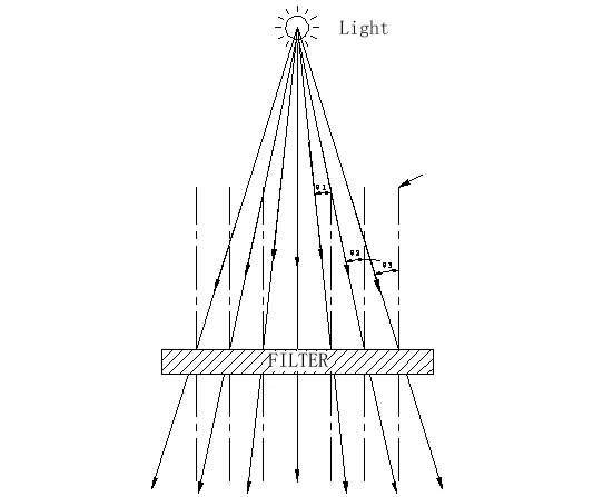
Do not mistake the incident Angle as the Angle between the light source position and the line between the center of the filter and the filter normal. Without a collimating path, even if the light source is placed on the center normal line of the filter, the light will still diverge, which means the incidence Angle will not be 0°.
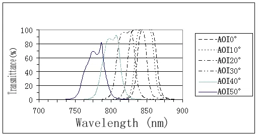
If the angle between the incident ray and the normal line of the filter has a certain range, then the specific range of the included Angle should be specified, because the design of the interference filter is very sensitive to the Angle, and for the narrow-band filter designed at 0°, if used at different angles, the effect will be completely different. Figure 3 takes 850nm narrowband filter as an example. When the incidence angle increases, the position of the central wavelength continuously moves to the short wave. As long as it is an interference filter, this Angle effect cannot be avoided, which is the basic characteristic of the interference filter. As can be seen from the figure, when a narrow-band filter of 850nm is used at 50°, it is no longer a narrow-band filter of 850nm, but a narrow-band filter of 770nm. Some users will reflect in the objects with wide Angle lens, add the narrowband filter, found only on the middle section of the object, is very dark, on the edge of thought among narrowband filter only, edge, that's the wrong understanding, narrow-band filter the entire surface is uniform, mostly because of the large Angle of incidence, filter the pervious to light band move towards shortwave, and shortwave part due to no light.
The above six parameters must be taken into account in the use and selection of narrow-band filters. Different performance indexes require different manufacturing costs of filters.





 EN
EN


