Definition of Cylinder Lens
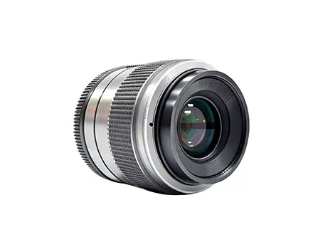
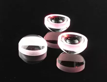
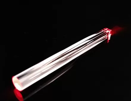
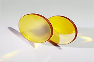
Cylinder lenses are lenses with different radii on the X and Y axes, hence the lens shape is cylindrical or semi-cylindrical, and only a single optical axis has image magnification. Cylinder lenses are commonly used as laser line generators, to adjust image height size, or to correct astigmatism in imaging systems.
Errors, Aberrations, and Specifications of Cylinder Lens
Any manufacturing process has its flaws, and the manufacturing of astigmatism cylindrical lens is no exception, so minor geometric errors are inevitable. Improper calibration during polishing can lead to some specific mechanical errors for cylinder lenses, resulting in optical distortion and negatively impacting performance. Therefore, it is crucial to strictly control these errors to ensure the performance of the cylinder lenses. ECOPTIK has achieved this with very strict and careful production processes to minimize unnecessary errors.
Wedge
In an ideal cylinder lens, the flat side of the lens is parallel to the cylindrical axis. The angular deviation between the flat side of the cylinder lens and the cylindrical axis is called wedge, usually measured in arc minutes. This angle is determined by measuring the thickness at both ends of the lens and calculating the angle between them. A wedge will cause the image to shift in a non-functional direction, like a wedge in window glass.
Coprimarity
In an ideal cylinder lens, the optical axis of the curved surface is parallel to the lens edges. The coprimarity error of a cylinder lens is the angular displacement of the optical axis relative to the lens edge, similar to the eccentricity of the functional surface in spherical optical elements. This coprim angle (α) causes the optical and mechanical axes of the lens to no longer be collinear, resulting in beam displacement. If the edge of the cylinder lens is used as a mounting reference, this error can make optical alignment very challenging. However, if the edge of the cylinder lens is not relied upon as a mounting reference, this error can be eliminated by offsetting the lens in the correct direction. The larger the diameter of a cylinder lens, the greater the associated edge thickness difference at a given coprim angle.
Axial Twist
Axial twist is the angular displacement between the cylindrical axis and the edge of the lens. Axial twist indicates the rotation of the functional surface of the cylinder lens relative to the outer diameter, causing the image to rotate around the optical plane. This situation is particularly detrimental to applications if the rectangular outer surface is fixed by its external dimensions. Rotating the cylinder lens to adjust the cylindrical axis can counteract axial twist.








 EN
EN
