Based on studying various propagation phenomena of light, various optical instruments have been designed and manufactured, such as microscopes for observing small objects, telescopes for observing distant objects, cameras, video cameras and so on.
There is usually an optical system in optical instruments, and its function is to image the observed object for observation by the human eye, or to detect it with photoelectric devices.
Optical systems usually consist of one or more optical elements. Each optical element is composed of a medium with a certain refractive index surrounded by a spherical, plane or aspherical surface.
An optical system in which the center of surface curvature of each optical element constituting the optical system is on the same straight line is called a coaxial optical system, and the straight line is called the optical axis.
There are also non-coaxial optical systems (e.g., spectrometer systems that include dispersive prisms or dispersive gratings).
All optical elements in an optical system are composed of spherical surfaces and are called spherical systems.
If an optical system contains an aspheric surface, it is called an aspheric system.
A single lens is the basic unit of a coaxial spherical system.
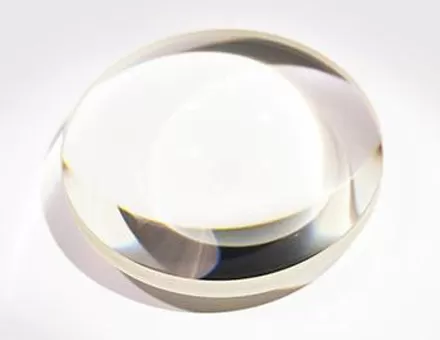
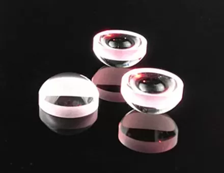
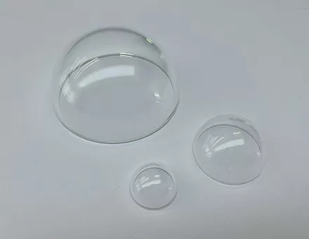
Lenses can be divided into two categories according to different shapes: the first category is called a converging lens or a positive lens, which is characterized by a thick middle and a thin edge; the second category is a diverging lens or a negative lens, which is characterized by a thin middle and thick sides.
According to the propagation law of light and wavefront, the propagation of light beam through the lens is studied.
(1) Converging lens or positive lens
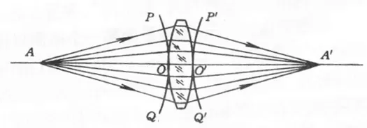
As shown in Figure 1, for a concentric beam emitted from point A, its wavefront PQ is a spherical surface with A as the center. When the light beam passes through the lens, since the refractive index of the glass is larger than that of the air, according to the relationship between the refractive index and the speed of light, the propagation speed of the light in the glass is smaller than that in the air, and the thickness of the center of the converging lens is larger than that of the edge, so the The central part propagates slowly, while the edge part propagates fast. In the case of Figure 1, when the light in the center propagates from O to O', the light in the edge has been propagated from P and Q to P', Q' respectively, the exit wave surface is bent from left to right, and the entire beam is folded towards the optical axis, called "convergence". If the lens surface chooses a proper curved shape, the outgoing wave surface may still be a spherical surface. The corresponding outgoing rays all intersect at point A', which is obviously the center of the outgoing spherical wave. A' is the "image point" formed by point A through the lens, and point A is called the "object point".
In Figure 1, A' is the intersection point of the actual light. If a screen is placed at A', a bright spot can be seen on the screen, and such an image point is called a "real image point".
(2) Diverging lens or negative lens
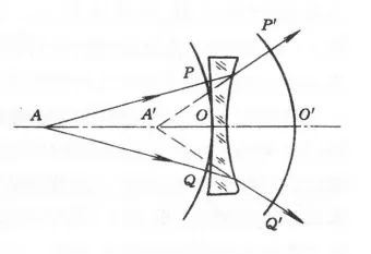
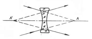
Since the edges of a diverging lens are thicker than the center, in contrast to a converging lens, the center part of the beam travels faster and the edges travel slower. as shown in picture 2. After the light beam passes through the lens, the wave surface bends to the left, and the corresponding outgoing light is deflected outward, which is called "divergence". If the outgoing wave surface is spherical, all the extension lines of the rays pass through the spherical center A' of the spherical wave. When looking behind the lens, what is seen is exactly the same as the light emanating from A', but cannot be displayed on a screen. Such image points are called "virtual image points".
In Figure 1 and Figure 2, the object point A is the starting point of the actual light, called "object point".
If the object point A is not an actual luminous point, but an image point of another optical system, before the light reaches point A, it encounters the first surface of the rear optical system and begins to change its propagation direction, as shown in Figure 3 shown. At this time, the actual light rays do not pass through point A, but their extension lines intersect at point A, which is called "virtual object point".
(3) Coaxial optical system
Let O1, O2, L, Ok denote an optical system with k faces, as shown in Figure 4.
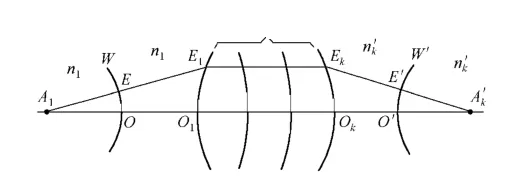
A spherical wave is emitted by a light-emitting point A1, and a concentric beam centered on the point A1 is emitted, and the point A is called the object point. If the spherical surface is still a spherical wave after passing through the optical system, that is, a concentric beam with the point Ak' as the center, and the point Ak' is also a geometric point, it is the perfect image of A1. Therefore, the condition for perfect imaging of the optical system is that when the incident is a spherical wave, the outgoing wave is also a spherical wave. Or according to Marius' law, the optical lengths between the corresponding points of the incident wavefront and the outgoing wavefront are all fixed values. Therefore, the optical length between the object point A1 and its perfect image point Ak' is a constant. For the optical system with k faces as shown in Fig. 4,

The space where objects are located (including real and virtual objects) is called object space; the space where images (including real and virtual images) are located is called image space. The two spaces are infinitely extended, not mechanically separated by a refractive surface or the left and right sides of an optical system.
However, the refractive index of the object space medium must be calculated according to the refractive index of the space medium in front of the system where the actual incident light is located; the refractive index of the image space medium must be calculated according to the refractive index of the space medium behind the system where the actual outgoing light is located. Calculate whether they are physical or virtual points, real or virtual image points.
For example, the virtual object point A in Figure 3, although it is located behind the system in terms of position, the refractive index of the object space medium is still calculated according to the refractive index of the medium in the space where the actual incident light pointing to point A is located (that is, the space in front of the lens). . Similarly, the refractive index of the medium in the image space corresponding to the virtual image point A' is calculated according to the refractive index of the medium in the space where the actual outgoing light rays are located (ie, the space behind the lens).
According to the theorem of reversibility of optical path, if the image point A' is regarded as a crop point, the light emitted by point A' must intersect at point A, and point A becomes the image formed by A' through the optical system. This correspondence between point A and point A' is called "conjugation".








 EN
EN


